Introduction: The classic laryngeal mask airway was invented by Dr Archie Brain in the UK in 19811. It became commercially available in the United Kingdom in 1988 and in the … Continue reading Newer Supraglottic Airway Devices

Introduction: The classic laryngeal mask airway was invented by Dr Archie Brain in the UK in 19811. It became commercially available in the United Kingdom in 1988 and in the … Continue reading Newer Supraglottic Airway Devices

Low dependency system Variable performance devices / low flow devices Fixed performance devices / high flow devicesChoice of delivery system is based upon: Degree of hypoxemia Requirement for precision of … Continue reading TECHNIQUES OF OXYGEN ADMINISTRATION
Introduction:
In 1936, *Magill* formally described the ‘sniffing position’ as elevation of the occiput and extension of the head at the atlanto-occipital joint. It is generally accepted as the best position for direct laryngoscopy.
*Bannister and Macbeth* refined direct laryngoscopy positioning by proposing a need for alignment of the mouth, pharyngeal, and laryngeal axes; later to be called the ‘three axes alignment theory’.
*Horton and colleagues* further developed this concept by determining ‘ideal angles’ for upper cervical flexion and lower cervical extension as 150 and 350, respectively.
Adnet and colleagues concluded that alignment of the three axes was impossible as shown in Figure 1 where the three axes are superimposed on one of the author’s MRI scans.
PRIMARY AND SECONDARY CURVES:
Traditional teaching in airway management includes the maxim that the oral, pharyngeal and tracheal axes must be aligned in order to achieve line of sight under the maxillary incisors to the glottis. More recently, magnetic resonance imaging (MRI) studies have shown that in reality, there is poor alignment of these three axes, even in the sniffing position (where the head is lifted and the neck extended). Such studies have led to most experts abandoning the three anatomical axes in favour of two anatomical curves to better describe the mechanics of airway management. The ‘primary’ oropharyngeal curve follows the superior surface of the tongue and ends in the laryngeal vestibule, where it meets the ‘secondary’ pharyngo-glotto-tracheal curve, which follows the trachea downwards. It can be seen from the figure that these curves form an ‘S’-shape (i.e they curve in opposite directions). These natural curves must be negotiated for successful tracheal intubation.


One of the authors (K.B.G.) has proposed an airway concept, the airway passage may be considered as a Be´zier spline (a parametric curve used to model smooth paths that can be controlled by adjusting a selection of points on the curve and the tangents to these points) rather than the alignment of three straight lines or axes. Although this curve is complex, we propose for clinical applications that it may be divided into primary (oro-pharyngeal) and secondary curves (pharyngoglotto-tracheal).
According to Figure 2, the point where these curves meet (i.e. the point of inflection) appears to be within the laryngeal vestibule—the space from the epiglottis to the glottis. First, successful direct laryngoscopy requires that the primary curve and the laryngeal vestibule align with the line of sight. This may be achieved by reducing the area between the line of sight and the airway curve. Secondly, tracheal intubation with a Magill-shaped tube is facilitated by aligning the direction of the laryngeal vestibule with the trachea.

For successful laryngoscopy, head and neck positioning should bring the line of sight as close as possible to all parts of the primary curve and the proximal section of the secondary curve between the point of inflection and the glottis. Therefore, the position with the smallest area between these two lines may be considered the optimal position, as it requires the least amount of tissue displacement during the dynamic phase of laryngoscopy.
The laryngoscope blade will flatten the primary curve completely reducing the area to zero and a line of sight to the glottis is created. Successful tracheal intubation is facilitated by the alignment of line of sight, the laryngeal vestibule, and the tracheal axis.
This configuration should produce a relatively straight passage through which a tracheal tube may pass. We have also assessed the effect of the anticlockwise rotation of the tangent to the point of inflection by measuring its angle to the horizontal plane (i.e. angle a) to see if this correlates with difficulty of laryngoscopy.

Head lift caused an anticlockwise rotation of (i) the line of sight and (ii) the tangent to the point of inflection on the MRI scans (Fig. 5), the latter being greater led to a resultant overall reduction in the area of the primary curve. The extension position leads to a clockwise rotation of the tangent to the point of inflection and a reduction in the primary curve area. The sniffing position countered the shift in the line of sight that occurred with head lift. This causes a further reduction in the area. These results support the sniffing position as the most favourable for direct laryngoscopy followed by extension, then head lift only, and finally the neutral position.

Head lift and sniffing positions caused a reduction in angle a due to an anticlockwise rotation of the tangent to the point of inflection. In these positions, therefore, a curved tracheal tube is more likely to pass from the supraglottic airway into the trachea without impacting on the anterior wall of the subglottic space. In the neutral and extension positions without head lift, this angle is not reduced and the upper part of the laryngeal vestibule is well below the glottis. These positions would predictably be associated with some difficulty performing tracheal intubation without the use of aides such as a bougie to negotiate the secondary curve.
In Nutshell:
The primary and secondary curves meet at an inflection point within the laryngeal vestibule (the space between the epiglottis and glottis). The tangent of the line joining the two curves at the inflection point is known as the ‘vestibule axis’ which itself is set at a variable angle depending on patient position and other factors. This is up sloping in the neutral position, making it more difficult to visualize the glottic opening and pass a tracheal tube. The sniffing position also has a beneficial effect on the vestibule axis, bringing it into a flat or down sloping position. When attempting intubation in the neutral position, for example, during manual in-line stabilistation, external laryngeal manipulation may flatten the vestibule axis, improving visualisation of the glottis and passage of a tube. However, the use of a bougie or stylet may still be necessary.
THE THREE AIRWAY COLUMNS:
The Three Column Model, developed by Keith Greenland (2008), groups the anatomical structures that affect airway management into 3 columns and can be used:

Posterior column (aka ‘posterior complex’)
Middle column (aka ‘air passage’)
Anterior column (aka ‘anterior complex’)
A triangular-shaped pyramid that contains the submandibular space, glossal muscles and laryngeal skeleton
The anterior column is displaced by the laryngoscope when it is placed in the mouth and moved in an attempt to expose the glottis; Greenland calls this the ‘dynamic phase’ of laryngoscopy (mouth opening and movement of the laryngoscope to achieve glottic exposure)
The anterior column is affected by any pathology that decreases the size of the pyramid or decreases the compliance of the tissues within it, as well as the range-of-movement at the temporomandibular joints and the stylohyoid ligament
A model of the head and neck for difficult intubation:
A better understanding of difficult intubation may be achieved by the development of a clinically accurate model that is able to explain individual cases of difficult intubation and to predict when difficulties will occur. In addition, the model should be able to suggest the best intubation technique for the type of difficulty encountered, including the type of laryngoscope and appropriate additional intubation devices. The components of such a model for direct laryngoscopy are shown in

Static positioning of the head and neck before laryngoscopy: the posterior complex:
Traditionally, the static positioning of the head and neck involves the appropriate alignment of the pharyngeal axis with the line of vision. The ability to position the patient’s head and neck optimally in the sniffing position is governed by the ability to flex the lower cervical spine, and extend the occipito‐atlanto‐axial complex. Overall, this may be referred to as the posterior complex.

Popitz described the occipito‐atlanto‐axial complex as having a range of extension of approximately 30°, limited in the normal patient by the anterior longitudinal ligament, the tectorial membrane and the ligamentum flavum. The atlanto‐occipital distance is the major factor which limits extension of the head on the neck in many cases, with the range of extension of the atlanto‐occipital joint alone being approximately 20° (with only 5° of flexion). This limited range of extension is therefore a significant factor in the static positioning of the patient, whether in the hyperextended or sniffing position for laryngoscopy.
Clinical conditions that involve cervical spine abnormalities, especially involving the occiput‐C1‐C2 spine, will predictably lead to difficult laryngoscopy. Rigidity of the cervical spine may be due to previous surgical fusion, pathological conditions such as rheumatoid arthritis and ankylosing spondylosis, or external stabilisation forces caused by axial traction, manual inline stabilisation, halo‐vest fixation, and hard (Philadelphia) cervical collars.
Dynamic phase of laryngoscopy: the anterior complex:
This phase predominantly consists of a number of movements. Essentially the mouth is opened and the mandible is anteriorly displaced. The submandibular space is also anteriorly displaced, as well as shifted laterally and partially compressed. Factors affecting this displacement frequently involve abnormalities of the mandible‐anterior neck area or anterior complex, which is mostly composed of the submandibular space and laryngeal skeleton.
The anterior complex of the neck may be considered an imaginary inverted triangular shaped pyramid (Fig). The three apices of the base are formed by the two temporomandibular joints and the bottom front incisors. The sides of the pyramid drop down and intersect at the hyoid bone (the apex). The base of the pyramid is the cephalic surface of the tongue and oral mucosa of the floor of the mouth and extends along the two rami of the mandible. The area below the hyoid is outside this pyramid, and is dominated by the laryngeal apparatus. The contents of this pyramid are composed of the submandibular space, subdivided by the mylohyoid muscle, which acts as a sling below the mandible, into the sublingual and submylohyoid spaces. The anterior muscular contents of the submandibular space are largely composed of the genioglossus muscle. Posteriorly are the hyoglossus, styloglossus and stylopharygeus muscles.

During the dynamic phase of direct laryngoscopy, the mandible is drawn forward and the muscle bulk of the submandibular space is compressed anterolaterally to provide a line of vision to the glottis. The ability of the anaesthetist to shift the submandibular tissues and the mandible anteriorly is dependent on the following:
Air passage:
Encroachment upon the airway may occur with a wide variety of conditions including foreign bodies, infective conditions such as epiglottitis, peritonsillar and retropharyngeal abscess, papillomatosis of the larynx, thermal injuries and neoplastic conditions.
The lateral pharyngeal walls are more ‘compliant’ than the soft palate and tongue and, if redundant, may lead to obstruction of the airway and obstructive sleep apnoea. In obese patients, adipose tissue is deposited from the nasopharynx to the laryngopharynx, increasing the likelihood of collapse of the pharyngeal walls during laryngoscopy. If the patient is obese and does not have obstructive sleep apnoea or other indicators of difficult airway, then the body mass index alone is not associated with difficult laryngoscopy.
AIRWAY ASSESSMENT AND PLANNING USING THE THREE COLUMN MODEL
Posterior column
Middle column
Anterior column

LEVITAN’S THREE-STAGE APPROACH TO TRACHEAL INTUBATION:
Thinking about the primary and secondary curves helps to explain difficulties with visualisation of the glottis (due to a pronounced primary curve and/or an up sloping vestibule axis) and with delivery of the tracheal tube (due to a pronounced secondary curve). Understanding this can therefore help us trying to overcome these difficulties, for example, with correct positioning, external laryngeal manipulation, and the use of stylets and bougies.
When managing these difficulties during the intubation attempt, it can be helpful to break tracheal intubation down into three stages as described by Richard Levitan:
It is essential to understand these three stages and that how we achieve them differs between airway devices.
STAGE 1: LARYNGEAL EXPOSURE:
Levitan suggests that Stage 1 should be a slow, methodical process, where the first objective is visualisation of the epiglottis (‘epiglottoscopy’). This structure will almost always be in the midline, and signals our first view of the laryngeal structures.
Levitan advises having a Yankauer sucker in the right hand during this process, to clear secretions, which might be masking the tip of the epiglottis from view.
How the epiglottis is reached depends on the device used, the difference being how the tongue (and therefore the primary curve) is negotiated. For example, the straight blade is directed lateral to the tongue and bypasses the primary curve, the standard Macintosh blade displaces the tongue to the left and flattens the primary curve, and angulated videolaryngoscopes follow the tongue in the midline and therefore follow the primary curve.
In all cases, the next step is to gain a view of the glottis
by either lifting the epiglottis directly (straight blade laryngoscopy) or indirectly, by deploying the hyo-epiglottic ligament with pressure in the vallecula (all other devices).
In all cases, the next step is to lift the tongue and other tissues of the anterior column with upward force in the axis of the handle of the laryngoscope, hopefully resulting in a full view of the glottic opening.
If not, Levitan advocates the use of bimanual laryngoscopy, whereby the intubator uses their right hand to manipulate the larynx into view. An assistant can then hold the larynx in the same position while the intubator moves on to Stage 2.
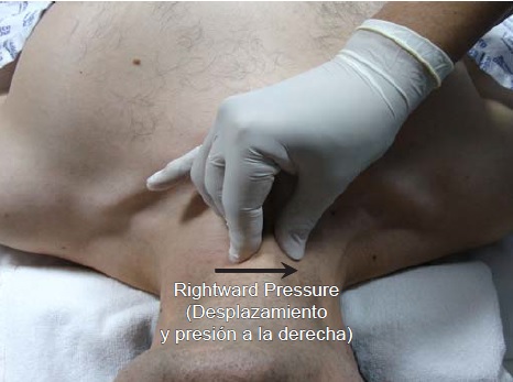
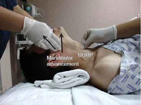
Bimanual laryngoscopy has been found to improve the view of the glottis more frequently than cricoid pressure, BURP (Backward Upward Rightward Pressure on the thyroid cartilage) or no manipulation in a cadaver model. Another manoeuvre, which can be used in difficult cases, is to lift the head further, either with the right hand or with the help of an assistant. This is contraindicated if there is cervical spine instability.
STAGE 2: DELIVERY OF THE TUBE OR BOUGIE TO THE GLOTTIC OPENING:
This stage is also dependent on the device used. Laryngoscopes that bypass or flatten the primary curve, by definition, result in a straighter line of sight to the glottis than those that follow the primary curve.
As a result, a tracheal tube can be advanced towards the glottis at a straighter angle than when using a non-channelled angulated videolaryngoscope. This explains why angulated videolaryngoscopes require a channel to guide the tracheal tube, or the use of introducers to aid tube delivery.
*If an angulated device is being used, it is important not to advance too close to the glottis – the larynx should not fill the entire monitor screen.*
In addition, at this point, angulated devices should be tilted slightly downwards, so that the glottic opening is seen in the upper half of the monitor screen, leaving the lower half for visualisation of the approaching tube or bougie. This has two main advantages. Firstly, the tube or bougie can be seen approaching the glottis and adjustments can be made to allow easy passage. Secondly, tilting the device results in a decreased angle between the laryngoscope blade and trachea, so that the tube or bougie will pass more naturally into the glottis.
The use of different laryngoscopes during Stages 1 and 2 is summarised in the table below.

For non-channelled devices, Levitan suggests inserting the bougie or tracheal tube into the right-hand corner of the mouth, then directing the tip posteriorly so that it comes into the line of sight (or monitor screen) from below. In this way, bougie or tube does not obstruct the view of the glottis until Stage 3 – advancement of the tube into the trachea.
STAGE 3: ADVANCING THE TUBE OR BOUGIE INTO THE TRACHEA
Successful passage of the tracheal tube again depends on the angle at which the tube is advanced, which again is device dependent. Angulated videolaryngoscopes present the tube at an angle where it is likely to impact on the anterior tracheal wall, necessitating the use of an introducer or channelled blade. Even then, other manoeuvres may be necessary for successful tube advancement. Bimanual laryngoscopy can be useful here, not only to bring the larynx into view but also to flatten the vestibule axis, facilitating tube advancement.
Other options to aid tube delivery are the use of specialised tracheal tubes (such as intubating LMA™ or Gliderite™ tubes), turning the tube 90 degrees clockwise at the level of the vocal cords (‘Right Turn for Rings’), an intubating stylet with a ‘straight to cuff’ angulation of 35 degrees or reverse loading of the tracheal tube onto a stylet.

THE LARYNGOSCOPES
The McCoy laryngoscope can improve the view at laryngoscopy.It seems to be especially useful in patients with limited neck extension (neck pathology or immobilisation by hard collar / in-line stabilisation).
Use of a Miller or Henderson straight blade for laryngoscopy is especially indicated when a long, floppy posteriorly directed epiglottis obscures the view of the larynx on first look with a Macintosh blade.A recurrent problem with the Miller blade is that the tracheal tube is often difficult to insert with this technique even when a good view of the larynx is obtained. It was for this reason that the Henderson blade was developed. This has an atraumatic tip and a ‘U’-shaped channel to allow for passage of the tube.
The polio blade is angled at 135 degrees to the laryngoscope handle. It can be of use in patients with large breasts or antesternal space restriction, and is most often used in obstetric anaesthesia. It is commonly fitted with a short handle that also helps to avoid the pronounced chest wall.
Standard blade videolaryngoscopes, such as the Storz™ C-Mac™ standard blade are becoming increasingly popular in airway management.
As yet, no single device has emerged as superior to the others, but videolaryngoscopes in general, seem to offer some advantages over conventional laryngoscopes. They have been shown to be useful in obese patients in particular, high-risk patients in general, during difficult direct laryngoscopy and after failed intubation.There is also growing evidence that videolaryngoscopes are useful for teaching airway management to novices.
Angulated blade videolaryngoscopes, such as the Storz™ C-Mac™ D-blade and the Ambu™ King Vision™ may be especially useful in cases where there is anterior column pathology (such that the primary curve cannot be modified by compression or displacement) or posterior column pathology (such that the secondary curve is also unfavourably positioned). These devices require the use of an introducer or channelled blade, and again can be useful for teaching airway management.
The Storz C-Mac D-Blade has a channel for a bougie on the left hand side of the blade, which can help to direct it into the glottis, a task that can otherwise be difficult with hyper-angulated blades.
TOP TIPS:
Ref:
1. K. B. Greenland. Airway Assessment Based on a three Column Model of Direct Laryngoscopy. Anaesth Intensive Care 2010; 38: 14-19
2. K.B. Greenland, M.J. Edwards, N.J. Hutton, V.J. Challis, M.G. Irwin, J.W. Sleigh,Changes in airway configuration with different head and neck positions using magnetic resonance imaging of normal airways: a new concept with possible clinical applications,British Journal of Anaesthesia,Volume 105, Issue 5,2010,Pages 683-690.
3. Greenland, K.B. (2008), A proposed model for direct laryngoscopy and tracheal intubation. Anaesthesia, 63: 156-161. https://doi.org/10.1111/j.1365-2044.2007.05326.x
4. Three Axis Alignment, Two Curve Theory and the Three Column Model. Chris NicksonNov 3, 2020. LITFL.COM
5. EMCrit Podcast 226 – Airway Update – Bougie and Positioning. June 13, 2018 by Scott Weingart, MD FCCM.
6. The CCAM approach to laryngoscopy: Alternative laryngoscopes: Videolaryngoscopy.

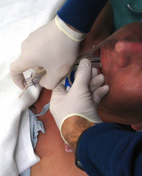
Although controversial, we routinely apply cricoid pressure (also known as Sellick’s maneuver) prior to and during RSII until confirmation of correct endotracheal tube placement. Despite conflicting evidence regarding the effectiveness … Continue reading CRICOID PRESSURE DURING RSII
LMA® Gastro™ Cuff Pilot™ is not made with natural rubber latex and phthalates. It is supplied sterile (sterilised by Ethylene Oxide) for single use only.
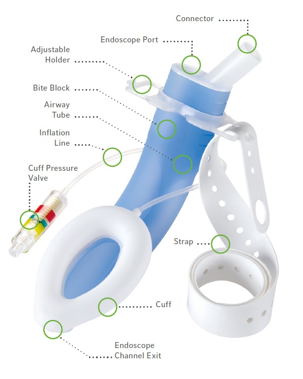
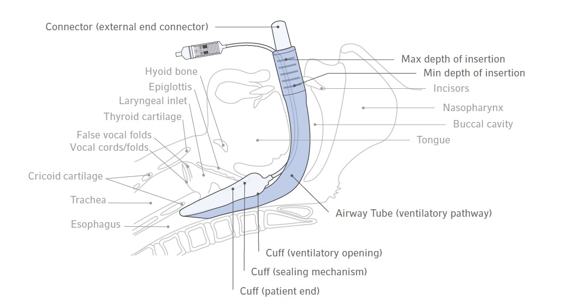
The device provides access to, and functional separation of, the respiratory and digestive tracts. The device contains a large bore endoscope channel which begins proximally and runs parallel along the airway tube. The endoscope channel ends at the cuff distal tip which communicates distally with the upper oesophageal sphincter (UES). A well lubricated endoscope (gastroscope or deuodenoscope) may be passed through the endoscope port for upper gastrointestinal endoscopy procedures.
The device provides easy insertion with the patient in the left lateral position without the need for digital or introducer tool guidance. It has dynamic flexibility to permit the device to remain in place if the patient’s head is moved in any direction. A built-in bite block reduces the potential for damage to, or obstruction of the airway tube or endoscope in the event of biting.
The device’s adjustable holder and strap fixation system maintain the device in a neutral position during endoscope manipulation. If correctly used it allows the anaesthetist to
be “hands free” of the device and enhances the seal of the cuff preventing leakage due to endoscope manipulation.
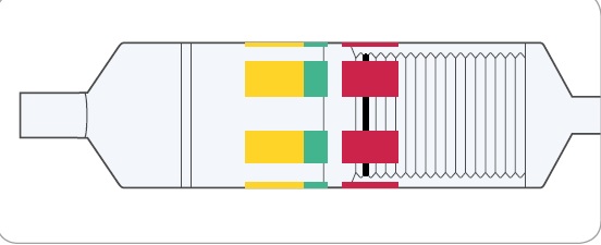
The inflation system of LMA® Gastro™ Cuff Pilot™ consists of an Inflation Line with Cuff Pilot™ Technology. Cuff Pilot™ Technology enables constant visualisation of pressure inside the mask cuff. It replaces the standard pilot balloon and is to be used in the same way for cuff inflation and deflation.
INFLATION SYSTEM OF LMA® GASTRO™ CUFF PILOT™
1. LMA® Gastro™ Cuff Pilot™ has a cuff pressure valve, which enables the end user to monitor the intra-cuff pressure of the mask through visual means while it is inserted in the patient’s airway. There are three pressure zones on the cuff pressure valve – Yellow,
Green and Red. The position of the black line on the bellows indicates the pressure within the cuff.
2. The Green Zone designates optimal pressure of the cuff, between 40 – 60 cm H2O. Air is introduced into the cuff until the black line is within this zone and a seal has been obtained.

3. The Yellow Zone indicates a pressure of less than 40 cm H2O. A seal may be obtained in the Yellow Zone; however, movement of the black line on the bellows into the Yellow Zone during the procedure may indicate a possible decrease in pressure or under-inflation.

4. The Red Zone indicates a pressure of more than 70 cm H2O. This indicates a possible increase in pressure or over-inflation. It is recommended that the pressure be reduced until the black bellows line is back in the Green Zone.
ANAESTHESIA MAINTENANCE
This device is well tolerated in spontaneously breathing patients when used with inhalational or intravenous anaesthesia, provided anaesthesia is adequate to match the
level of surgical stimulus, and the cuff is not over-inflated. During Positive Pressure Ventilation (PPV) when using this device, tidal volumes should not exceed 8 ml/kg, and peak inspiratory pressures should be kept below the maximum airway seal pressure.
USE OF THE ENDOSCOPE CHANNEL
For gastroscopy, it is recommended to pass the endoscope under vision through the device (this will not be possible with the duodenoscope).
The primary function of the endoscope channel is to allow an endoscope to be passed through the device.
The secondary function of the endoscope channel is to provide a separate conduit from and to the alimentary tract. It may direct gases or liquids from the patient.
Observational Study:
Ref: Efficacy of a new dual channel laryngeal mask airway, the LMA®Gastro™ Airway, for upper gastrointestinal endoscopy: a prospective observational study.
The “Up–Down” Movement
The second step also may be used to increase the “seal pressure” for positive pressure ventilation and may help protect the airway if regurgitation inadvertently occurs.
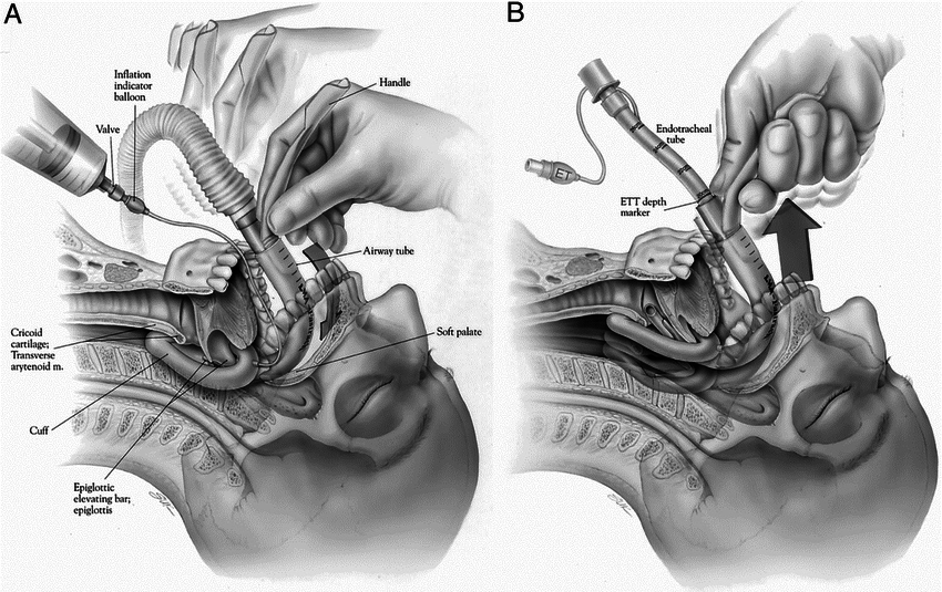
The Bailey Maneuver
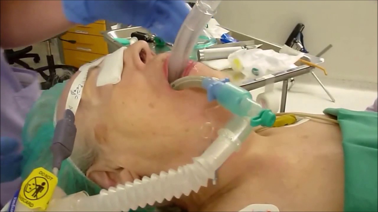
The exchange of an ETT for a laryngeal mask airway (any version) at the end of a long surgical procedure provides an excellent airway during emergence from anesthesia for a patient who has fasted. Paul Bailey, consultant anesthetist at the Royal National Throat, Nose and Ear Hospital in London, first recognized and described this exchange. Toward the end of surgery, with the patient still under “deep” anesthesia and following oropharyngeal suction, a laryngeal mask device is inserted behind the ETT and its cuff inflated. The ETT cuff is deflated and the tube removed. The patient is ventilated through the mask airway. The mask airway is left in place until the patient regains consciousness and is able to remove the mask airway when prompted verb ally. The laryngeal mask airway, when properly inserted (with a cuff pressure of 60 cm H2O or less) provides a clear airway without desaturation, coughing, bucking or straining, and with a minimal cardiovascular response that facilitates a smooth return to consciousness.
Source: C HANDY VERGHESE , MBBS, FRCA Consultant in Anaesthesia and Intensive Care, Royal Berkshire NHS Foundation Trust, Reading, Berks, U.K.
A child with laryngospasm can be a scary thing to manage. There’s no way to predict whether a child is going to get it.
You can try the usual maneuvers including a jaw-thrust, positive pressure ventilation to try to open the vocal cords, and suctioning. If these don’t work, you might consider giving the patient a paralytic, such as succinylcholine, and performing an endotracheal intubation for worsening hypoxia. Before that, what non-invasive maneuver can you try first?
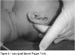
Laryngospasm notch maneuver
This method involves the application of digital pressure at the “laryngeal notch”.
This notch is located behind the lobule of the pinna of each ear. It is bounded anteriorly by the ascending ramus of the mandible adajacent to the condyle, posteriorly by the mastoid process of the temporal bone and cephalad by the base of the skull.
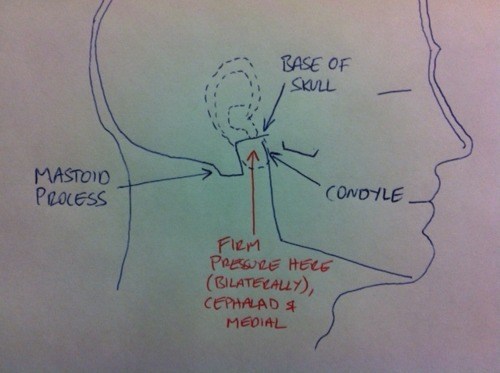
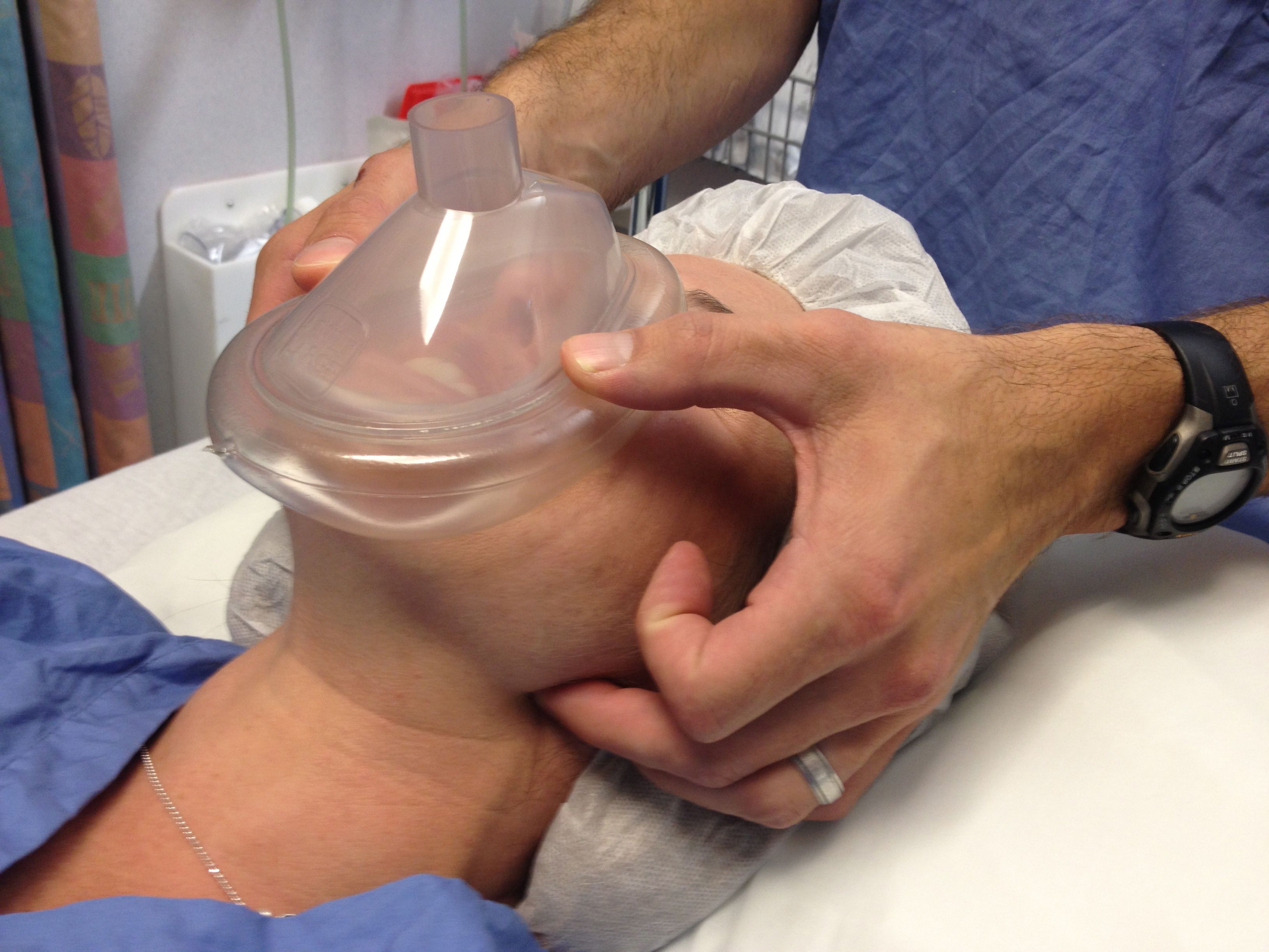
The therapist presses very firmly inwardly toward the base of the skull on each side using either the index or middle fingers while at the same time lifting the mandible at a right angle to the plane of the body (forward displacement of the mandible or jaw thrust).
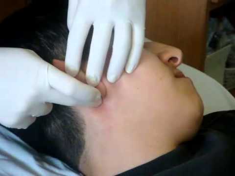
Paediatric unilateral:
Adult bilateral:
Why does it work?
Ref:
CLINICAL ANESTHESIOLOGY G.Edward Morgan 3rd Edition
OVERVIEW

PROCEDURE
UTILITY
Lifeinthefastlane.com
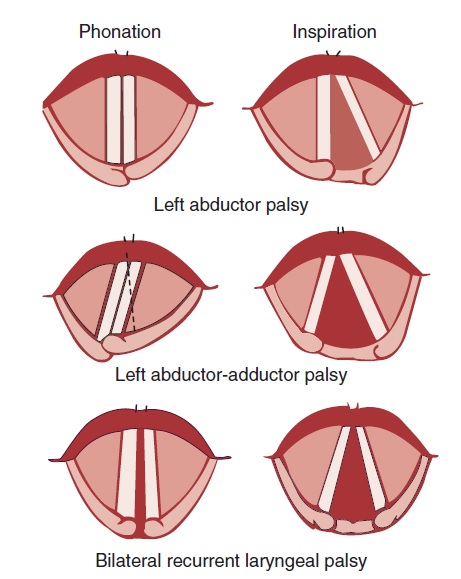
The recurrent laryngeal nerve carries both abductor and adductor fibers to the vocal cords.
The abductor fibers are more vulnerable, and moderate trauma causes a pure abductor paralysis (Selmon’s law).
Severe trauma causes both abductor and adductor fibers to be affected.
Pure adductor paralysis does not occur as a clinical entity.
In the case of pure unilateral abductor palsy, both cords meet in the midline on phonation (because adduction is still possible on the affected side). However, only the normal cord abducts during inspiration.
In the case of complete unilateral palsy of the recurrent laryngeal nerve, both abductors and adductors are affected. On phonation, the unaffected cord crosses the midline to meet its paralyzed counterpart, appearing to lie in front of the affected cord. On inspiration, the unaffected cord moves to full abduction.
When abductor fibers are damaged bilaterally (incomplete bilateral damage to the recurrent laryngeal nerve), the adductor fibers draw the cords toward each other, and the glottic opening is reduced to a slit, resulting in severe respiratory distress.
However, with a complete palsy, each vocal cord lies midway between abduction and adduction, and a reasonable glottic opening exists. Thus, bilateral incomplete palsy is more dangerous than the complete variety.
Source: Benumof and Hagberg’s Airway Management – 3rd Edition